
This places the depletion-type, or simply D-type, IGFET in a category of its own in the transistor world. When there is zero voltage applied between gate and source, the IGFET will conduct current between source and drain, but not as much current as it would if it were enhanced by the proper gate voltage. Illustrating the proper biasing polarities with standard IGFET symbols: That is to say, it takes just the opposite polarity as an N-channel IGFET to either deplete or enhance:
#Igfet transistor power transistor free
Think, “negative (-) correlates with N-type, thus enhancing the channel with the right type of charge carrier (electrons) and making it more conductive.” Conversely, if the input voltage is connected to an N-channel IGFET the other way, so that negative (-) connects to the gate while positive (+) connects to the source, free electrons will be “robbed” from the channel as the gate-channel capacitor charges, thus depleting the channel of majority charge carriers and making it less conductive.įor P-channel IGFETs, the input voltage polarity and channel effects follow the same rule. If the IGFET is an N-channel and the input voltage is connected so that the positive (+) side is on the gate while the negative (-) side is on the source, the channel will be enhanced as extra electrons build up on the channel side of the dielectric barrier. The key is to consider the type of semiconductor doping used in the channel (N-channel or P-channel?), then relate that doping type to the side of the input voltage source connected to the channel by means of the source lead. Understanding which polarity has which effect is not as difficult as it may seem.

Input voltage polarity determines which way the channel will be influenced. This type of IGFET, although its called a “depletion-type,” actually has the capability of having its channel either depleted (channel narrowed) or enhanced (channel expanded). The insulated gate allows for controlling voltages of any polarity without danger of forward-biasing a junction, as was the concern with JFETs. Reversing the controlling voltage’s polarity has the opposite effect, attracting the depletion region and narrowing the channel, consequently reducing channel conductivity: In an N-channel IGFET, a controlling voltage applied positive (+) to the gate and negative (-) to the source has the effect of repelling the PN junction’s depletion region, expanding the N-type channel and increasing conductivity: In other words, the channel’s effective width changes just as with the JFET, but this change in channel width is due to depletion region displacement rather than depletion region expansion. Indeed it is, for when a controlling voltage is applied between gate and source, the conductivity of the channel is changed as a result of the depletion region moving closer to or further away from the gate. JFET operation is based on the expansion of the PN junction’s depletion region, but here in the IGFET that cannot happen, so IGFET operation must be based on a different effect. As a result, a depletion region exists between the two materials, but it can never be expanded or collapsed. This connection prevents any voltage from being impressed across the PN junction.

With source and substrate common to each other, the N and P layers of the IGFET end up being directly connected to each other through the outside wire.

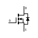
Usually, this connection is made internally to the IGFET, eliminating the separate substrate connection, resulting in a three-terminal device with a slightly different schematic symbol: In practice, the substrate lead is directly connected to the source lead to make the two electrically common. Notice also how there are four connections to the IGFET. There are other types of IGFET construction, though, and so “IGFET” is the better descriptor for this general class of transistors. Due to this Metal (gate) - Oxide (barrier) - Semiconductor (channel) construction, the IGFET is sometimes referred to as a MOSFET. That barrier is sometimes made from silicon dioxide (the primary chemical compound found in sand), which is a very good insulator. Notice how the source and drain leads connect to either end of the N channel, and how the gate lead attaches to a metal plate separated from the channel by a thin insulating barrier. Here is a diagram of an N-channel IGFET of the “depletion” type: There is a PN junction inside the transistor, but its only purpose is to provide that nonconducting depletion region which is used to restrict current through the channel. Insulated gate field-effect transistors are unipolar devices just like JFETs: that is, the controlled current does not have to cross a PN junction.


 0 kommentar(er)
